Thin Film Devices, Inc. is the leading manufacturer of glass heaters for the flat panel display industry. Typically, heaters are I.M.ITO™ to epoxy or air, for stand alone or lamination versions. The heater designed for 0.1 Watt/Sq. Inch – 5 Watt/Sq. Inch.
TFD has developed a unique software process to predict heat dissipation, power loading and temperature rise, in different sets of environments, for ruggedization.
TFD is also a leading heater manufacturer for sapphire and silicon substrates using accumulation of metal and/or oxide in a grid pattern, which can be powered up to 20 Watts/Sq. Inch, with transmission up to 95%, in the ranges of 0.8µm – 6.5 µm. An ideal choice for NIR and IR applications.
| Glass | Corning Eagle XG, Eagle 2000, Borafloat, Standard float (soda-lime) |
|---|---|
| Tempered Glass | Chemical or Heat Tempered |
| Thicknesses: | 0.01" (0.25 mm) to 0.5" (12.7 mm) standard. (For others, consult TFD) 70 µm & 100 µm On Special Request |
| Plain Version: | All from 1/2" sq. or round, to 24” x 24" (610 mm x 610 mm) |
|---|---|
| Patterned: | Sizes from 1/2" sq. to 14” x 18" (355 mm x 457 mm) |
| Many Custom Variations Available: (consult TFD) |
Circular domes Curved plates Wide variations on voltage and power are possible |
| Tolerances for sizing:± 0.002" (0.05 mm) | |
Process:
Ion Beam Sputtering (Superior Process)
Applications:
Commercial Displays, Avionics and Military Displays
Coating Non-Uniformity
± 2.5% across full sheet
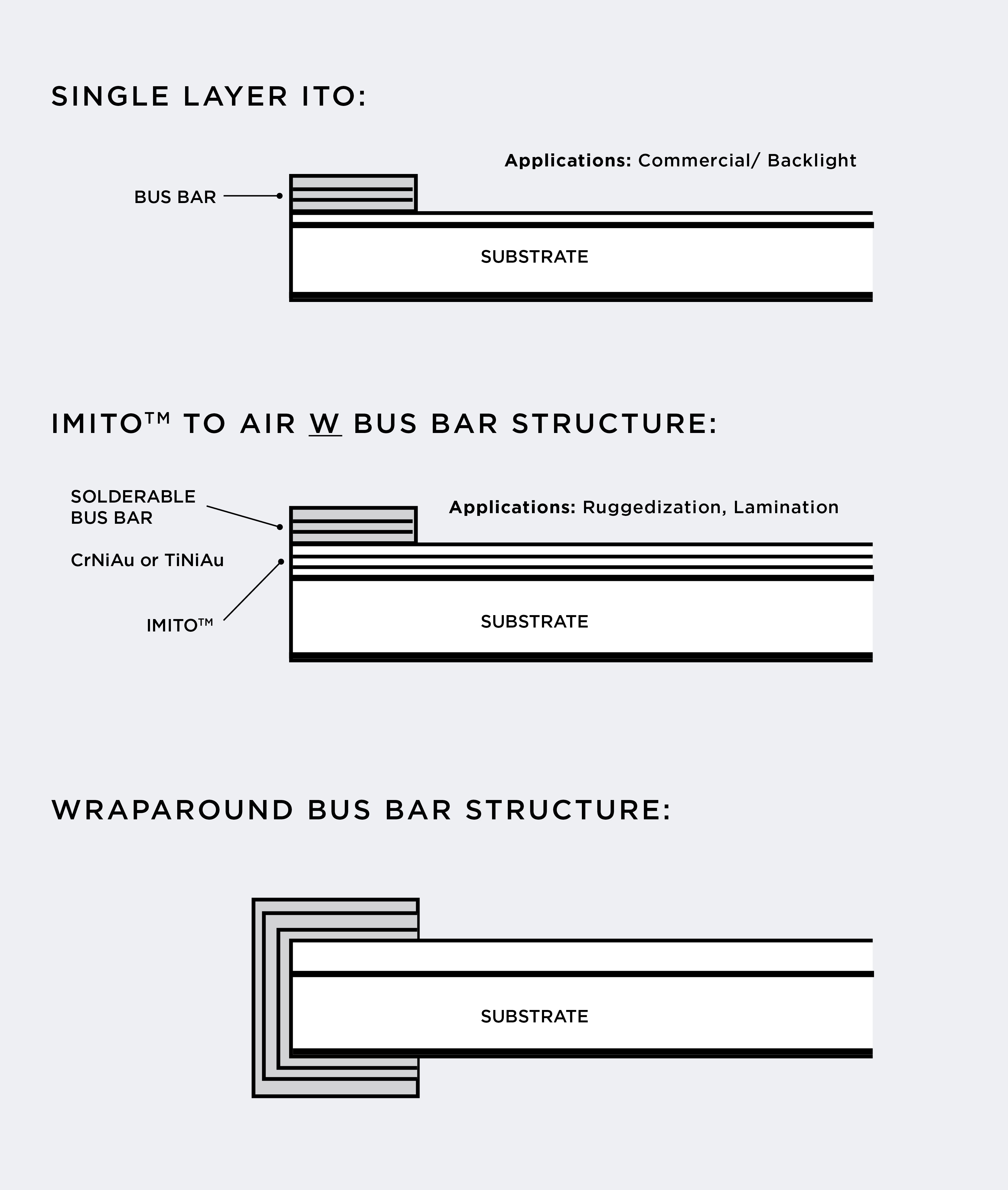
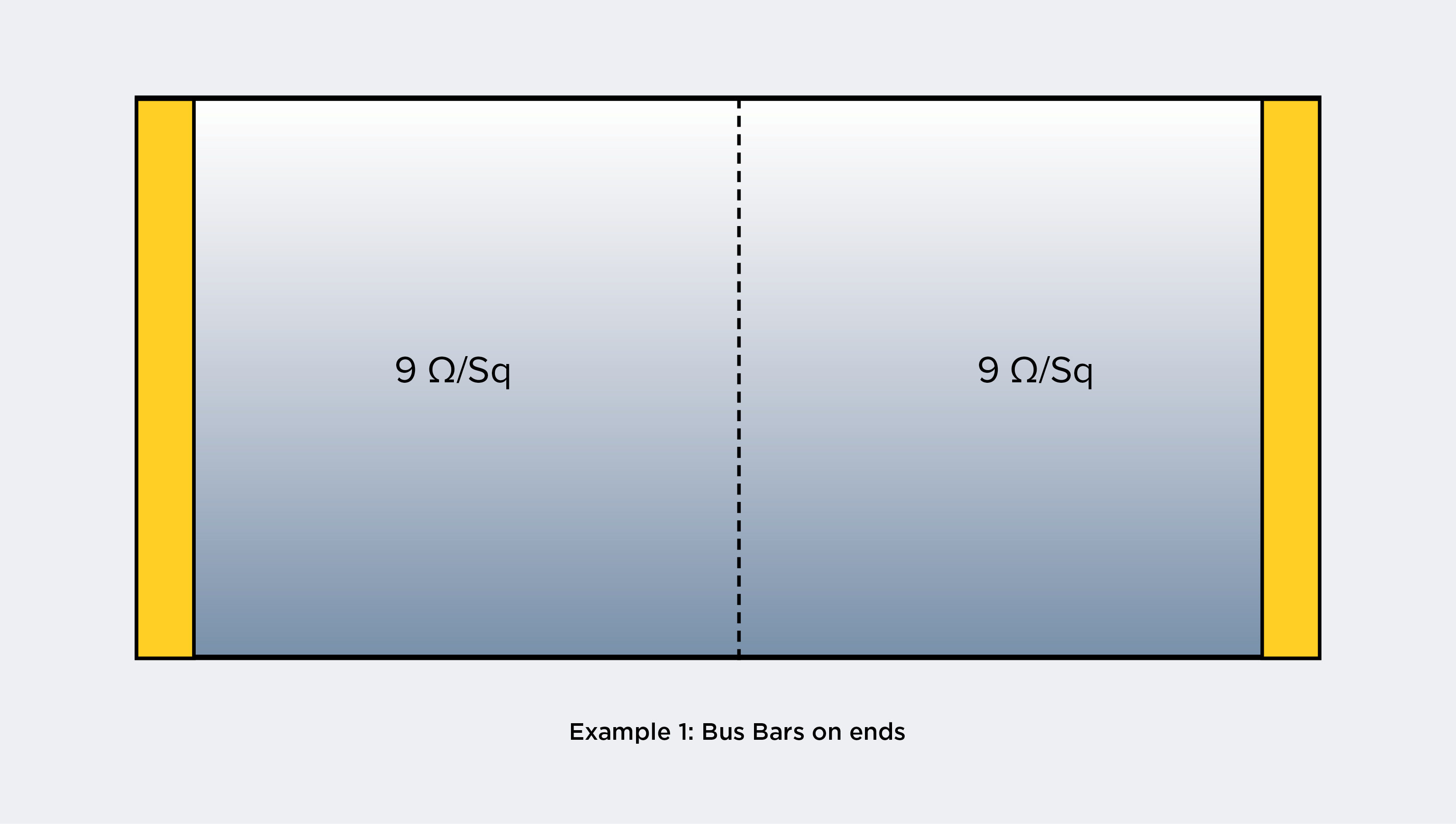
BusBars:
1: Sputtered Cr/Ni/Au, Solder reflow, 10K PSI (pull test)
2: Flex Cable
3: Wraparound (see diagram)
Surface Quality:
- Defects: < 5 micron on large substrates
- Imbedded Particle < 2 micron
- Surface Roughness: < 20 Å RMS, for each side
- Inspection Quality:
80/50 to 20/10 (5K Lux)
Thermal Imaging
Durability:
Abrasion: 200 strokes @ 10Kgm (Mil C-675)
Adhesion: Snap Test (Mil M-13508)
Solubility: > 24 hours in Sodium Chloride, Fog and Solution (Mil C-675)
Temperature: > 12 hours @ -55 to 350°C
Packaging:
Class 100, or as required.
| Tested Power Rating: | 0.05 to 20 watts /sq.in. (Configuration dependant) |
|---|---|
| Heating Uniformity: | Sizes from 1/2" sq. to 14” x 18" (355 mm x 457 mm) |
| Heater Types: | Plain I.T.O. | I.M.ITO™ | I.M.ITO™ | Grid / Patterned |
|---|---|---|---|---|
| Transmissions: * | 75 – 85% | 85 94% | * 90 – 98% | IR 90% |
| Vs. Wavelength: | 400-700nm | 400-700nm | 400-700nm | 1 – 10 µm |
| Resistivity, nominal (ohms/sq.) | 2 to 350 | 2 to 350 | 2 to 350 | 5 to 50 |
| * ITO Thickness Dependent | ||||
| Resistivity (Ohm – Cmm) |
Thickness Å | TCR Thermal Coefficient of Resistivity |
General Nature | |
|---|---|---|---|---|
| ppm@25˚C | ||||
| ITO Transparent | 1.5x10 -4 | 1500 Å | 1500+200 | Transparent |
| SiOiCr | 7.2x10 -4 | 1500 Å | 100+25 | Black |
| Inconel | 4.5x10 -4 | 1500 Å | *150+25 | Metal (grid) |
| NiCr | 3.5x10 -4 | 1500 Å | *300+50 | Metal (grid) |
| TaN | 4.5x10 -4 | 1500 Å | *100+50 | Ceramic |
| AI | 4.6x10 -6 | 1500 Å | 450+50 | Metal (grid) |
| Others Available Upon Request | ||||
Resist Equation
For the final manufacture of a heater, the resistance for the heater (ohms) is converted to resistivity (*ohms/sq.)
This value is a function of the length of the heater (L) and the width (W) as it relates to the total resistance. L is the size between bus bars.
p(Resistivity) Ohms S/SQ. = R (Resistance) Total in Ohms x (B + L)
The Heater consumes power per Ohms Law: P= E2 + R
BusBar Coatings
TFD offers several solutions of low profile, solid state and silver bus bars completely compatible for all solvents and pull tests of 8K gram/sq in.
A. Metalized Busbar. Cr / Ni / Au Solderable
B. Silver Epoxy
C. Copper Tape
Transparent heaters are essential to use for challenging environments for cameras, LCD’s & electro-optical devices below -10ºC. The application in Avionics, cameras, LCD’s & locomotives require heaters so they can operate in cold and severe climates. Applying a heater is the simplest solution. The transparent heater is usually made by only I.T.O. or I.M.I.T.O. ™ with higher transmittance. The resistance of the heater determines the rate of heat required and power utilization. The lower the resistance, it requires higher power and higher rates of heating.
TFD, Inc. has pioneered the use of I.T.O. and I.M.ITO ™ with BBAR coatings for efficient and high performance heaters for avionics, locomotives, flat panel displays, ships and cameras. The heating uniformity and burned out is controlled by very low resistive bus bar material with low contact resistance.
The heaters can be designed for wide resistance from 300 – 5 ohms and voltages (115, 28, 24, 12 volt). The heater with I.T.O. or I.M.ITO ™ has been tested up to 10 watts per square inch. Usually a much lower heat is used for LCD display applications. The bonded heaters require less power than stand alone, typically 1/3. The I.T.O. and I.M.ITO ™ coatings are extremely reliable and stable for continuous operations. The typical visible transparency for I.T.O. is ≥ 80% avg., and IMITO™ is ≥ 92% average.
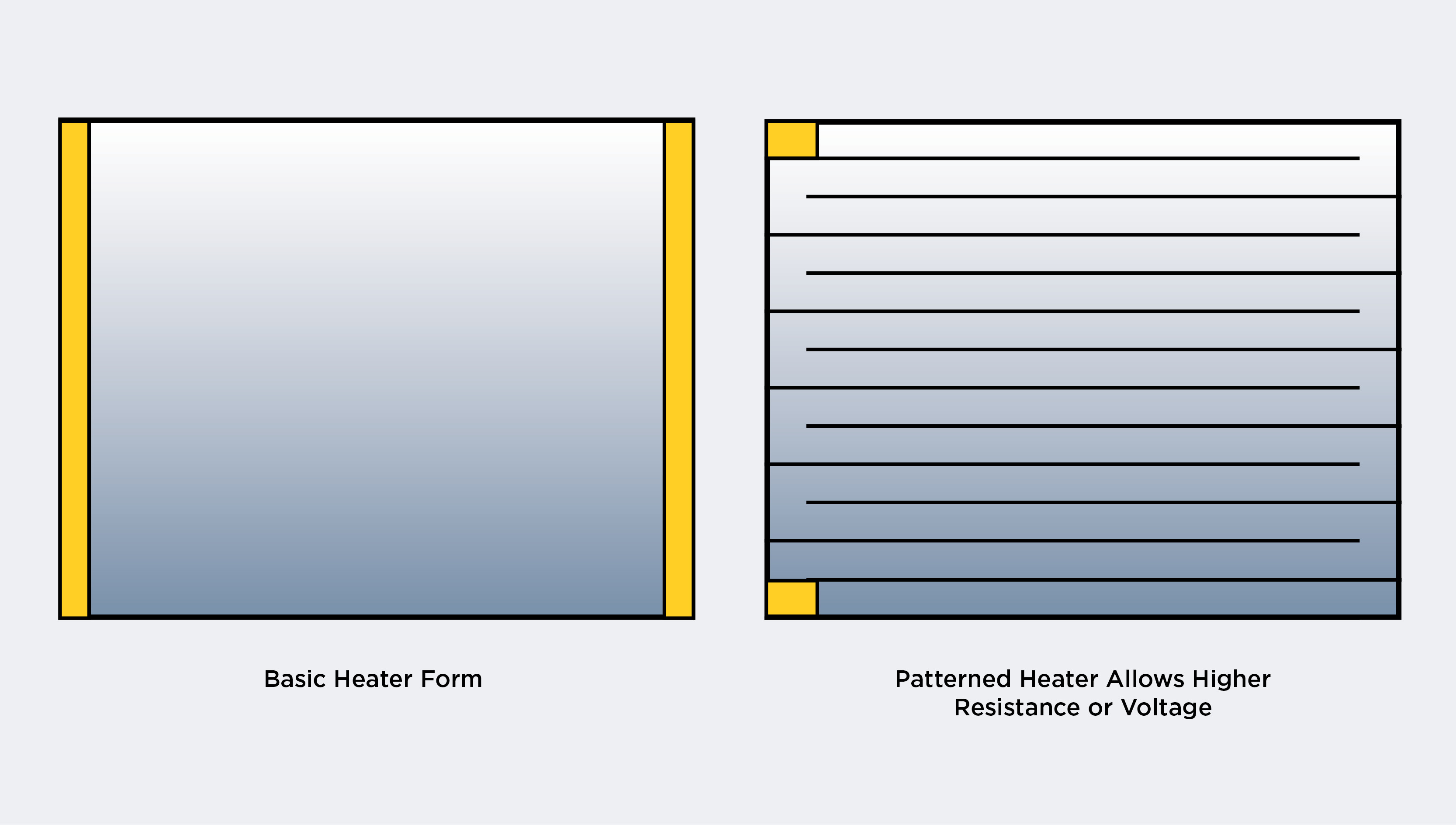
The patterned heaters are commonly used for uniquely higher or lower powers, ≥ 10 watts/sq. inch. TFD can design patterned for various shapes, & sizes while maintaining uniform heating.
The patterned heaters are also very desirable for Infra-Red (IR) applications for wavelengths of 1.0 µm – 12 µm.
Connection: Bus bar to heating surface.
The contact resistance from the bus bar to the heating surface, I.T.O., I.M.I.T.O. ™, or NiCr must have ≤ 0.1 ohm. The other rule of thumb is to have individual bus bar resistance to be ≤ 5% of the total resistance of the heater. The bus bar materials are:
A. Silver Epoxy B. Soldered Metallization C. Silver Frit Material
The Silver Epoxy is inexpensive and decays in 2 – 3 years. The Silver Frit Material has to be fired at ≥ 350°C which deforms glass flatness and this process contaminates the surface. The Metalized Bus bar, such as Cr/Ni/Au, is a solid state process and works extremely well with Soldered bus bar heaters. This is a highly recommended process. (See Heaters – 1 Page).
Power Calculation:
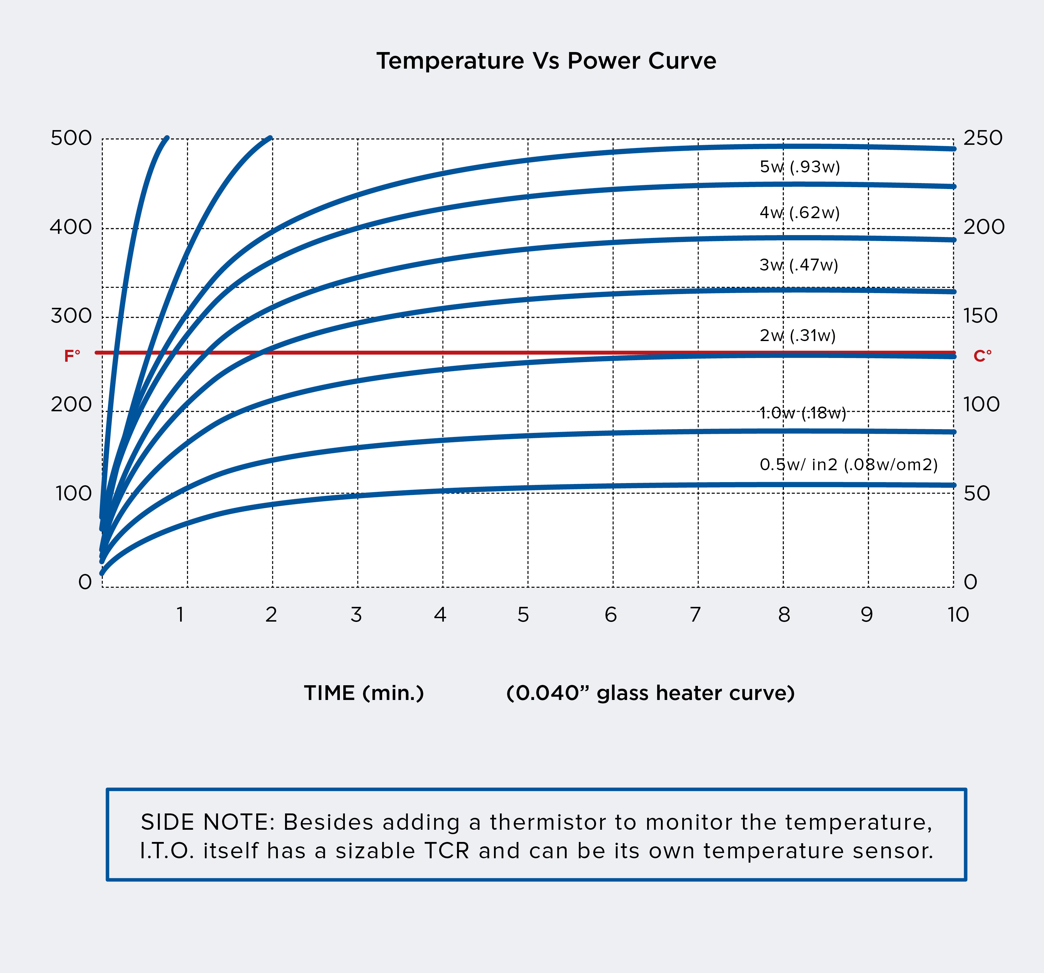
Below a Temperature Rise curve is provided that gives the relationship of time versus power of the heater with thickness 0.040”. There are different ways to apply heater glass with displays: A. Stand alone. B. Laminated. The standalone are typically applied in the back of the displays and have air gaps, 0.008” – 0.020”, which makes it a poor heating system. For low heat requirements it’s plenty. For fast rise temperature the heater glass should be bonded for optimum avionics applications.
Mounting heater glass on the front (viewing side) of the display is not recommended as heat loss to air could be as high as 50% of the total heat.
A thermistor or I.T.O. / Thermal coefficient of resistance (TCR) is commonly used to control temperature.
If higher temperatures are used to quickly heat the display, you must reduce that heat level once at operating temperature. Additionally, it is not recommended to operate heaters above a 20°C ambient temperature.
| Resistivity |
Thickness Å | TCR/PPM | General Nature | |
|---|---|---|---|---|
| I.T.O. | 1.5x10 -4 | 1500 Å | 1500 ±250 | Transparent |
| Sn02 | 3.5 x 10 -4 | 1500 Å | 1500 ±100 | Transparent |
| NiCr | 3.5 x 10 -4 | 1500 Å | 300 ±50 | Opaque |
| TaN | 4.5x10 -4 | 1500 Å | 150 ±50 | Opaque |
| Inconel | 4.5x10 -4 | 1500 Å | 225 ±50 | Opaque |
| Si0iCr | 7.2 x 10 -4 | 1500 Å | 150 ±50 | Opaque |
| Power Recommendation | Application | |
|---|---|---|
| 1. Silver Epoxy | ≤1.5 watt/sq inch | Commercial Heaters |
| 2. Silver Epoxy with Copper Strip | ≤2.0 watt/sq inch | Commercial/Industrial |
| 3. Sputtered Cr/Ni/Au | 1 – 10 watt/sq inch | Avionics, Ruggedized |
| 4. Silver Frit | 2.5 – 5 watt/sq inch | Commercial/ Industrial |
For example, for dew removal we might use only ¼ W/sq. inch in a 2 x 4 inch heater pattern on glass. With the 8 square inches, a total of 2 watts is required since the chart values are Watts/sq. in. (8 x ¼ = 2). This information and the intended heater voltage allow calculation of the heater resistance. The formula follows:
|
Heater Resistance (R) =
|
E2 | (Voltage, in Volts) | |
| P | (Power, in Watts) |
To complete the Example, we’ll use 6 Volts to power the heater. So, R becomes 18 ohms (6, squared, divided by 2).
Now the heater resistance and part sizes are all that’s required to define a heater to TFD; But there, heater resistance is converted into resistivity for production purposes. Resistivity is the surface resistance nature the manufacturer coats so the part shows the correct resistance. To determine the resistivity value, it’s calculated with the length (L) and width (W).
(Note: Length is always the distance between bus bars, even if smaller than the width).
|
Resistivity ( ρ )
|
= | L x R | |
| W |
| L = Length (either inch or cm) | W= Width (either inch or cm) |
| R = Heater Resistance (ohms) | ρ = Resistivity (ohms/sq.) |
Process: Sputtering
Heater Coating Materials:
The most commonly used transparent resistive coatings are I.T.O. (Indium Tin Oxide), and tin oxide. TFD concentrates on producing superb quality I.T.O. and IMITO™, in a variety of forms. Opaque conductor films are Aluminum, Nichrome, Inconel, Tantalum, Nitride and cermet films. Substrate materials can be glass, quartz, ceramic, plastic, kapton, polyester and others.