Transparent Conductors (TCO) available with many different thicknesses and resistances.
Ratio 90-10 / 95-5 mole percentage
Neutral Yellow in color
Standard resistances: 1 ohm/sq – 500 ohm/sq
I.T.O continues to be king among all transparent conductors. Most commonly used in all flat panel displays, LCD, Oled, LCO’s, touch screens, P-caps, heaters, EMI-shielding, circuits, MEMS and solar applications.
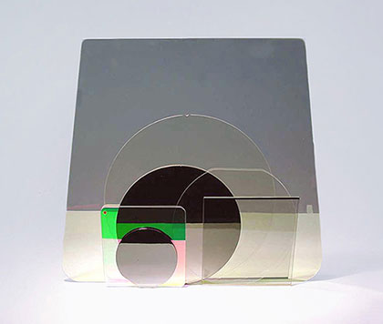
Micro Displays, Electro-optical devices
Ratio 91-9 mole percentage
Yellowish in color
Standard resistances: 10 ohm/sq – 300 ohm/sq
Since the beginning 2002, it’s usage as a substitute for I.T.O. (in the LCD Market) has diminished in current years. It is easily etchable, but not as environmentally durable as I.T.O. I.Z.O. .Exhibits poor water stability with time and temperature, and is very sensitive to wet chemistry.
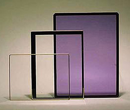
Wideband TCO, OLED
2% mole percentage of Al in Zinc Oxide
Neutral – Yellow in color
Standard resistances: 30 ohm/sq – 2000 ohm/sq
Commonly used for capacitive touch screens and other high resistive applications, such as antistatic discharge. A.Z.O. is an old technology commonly used for CRT.
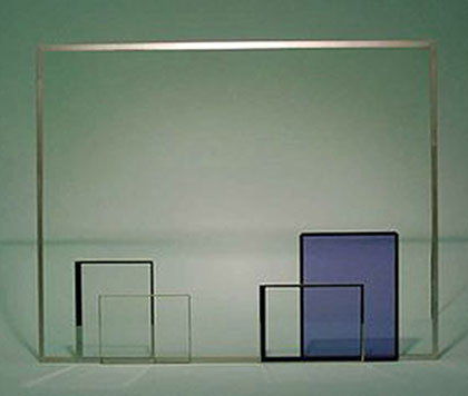
High Resistance TCO, Solar Products
Neutral color – Hazy in color
Standard resistances: 7 ohm/sq – 30 ohm/sq
F.T.O. is the most stable, durable, and robust, as well as the oldest transparent conductor. It can only be produced by CVD process and can be difficult to etch fine patterns ≤50 µm. F.T.O. was primarily used for plasma displays and low E architecture glass applications. It is now much more common to see it’s usage in solar panels such as CIGS.
TFD has been able to coat F.T.O. on glass as thin as 0.7&1.1 mm on a routine basis.
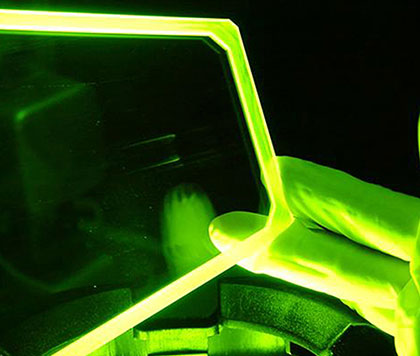
Organic Photo-voltaic
Custom mixed TCO from 400nm-2500nm
Neutral – Light Yellow in color
Standard resistances: 10 ohm/sq – 50 ohm/sq
TFD has developed this unique, low resistance but highly durable coating for wide range of wavelength from 400-2500nm..
WRTCO™ at 1550nm C-Band
TFD pioneered and invented Planar Ion Beam Sputtering (IBS) for large area coating process. This technique is different than plain magnetron sputter process. (For superior than Ion beam Assist e – beam)
This process provides very low surface roughness, i.e. I.T.O. (RMS ≤ 7 Angstroms @ 1450 Angstroms and higher work function (W.F.) ≥4.8 ev)
This is an excellent choice to manufacturing devices such as Oled, MEM’s & Organic Solar (OPV)
The IBS process provides an excellent adhesion, abrasion, higher compact density ≥ 99% and extremely stoichiometric, where E-Beam and Ion assisted E-Beam cannot match the quality
| TFD Produced TCO's vs Competition | |||||||||
|---|---|---|---|---|---|---|---|---|---|
| Figures of Merit | T.F.D., IBS Process | E-beam with Ion gun | |||||||
| IBS Ion-Beam Sputtering |
Bulk Resistance ohm/cm |
Thickness Å | Resistivity @ 250°c | Resistivity @ 60°c | T% after crystallization at 550 | ASIS T% @ 550 nm | @250 ±25 T% color Visual | Figure of Merit | Figure of Merit |
| I.T.O. a.90:10 |
2.0 x 10⁻⁴ | 1450 ±100 | 15±3 | 25±3 | 88% | 85% | Clear/ Neutral | 89.2 | 73 |
| b.95:5 | 1.8 x 10⁻⁴ | 1450 ±100 | 12±3 | 20±3 | 88% | 85% | Clear/ Neutral | 89.0 | 74 |
| I.Z.O. | 3.5 x 10⁻⁴ | 1450 ±100 | 20±5 | 40±5 | 85% | 82% | Very Yellowish | 44.84 | Not Available |
| A.Z.O. | 3.5 x 10⁻³ | 1450 ±100 | ≤100 | ≤300 | 85% | 83% | Clear/ Neutral | 4.48 | Not Available |
| F.T.O. | 4.0 x 10⁻⁴ | 1450 ±100 | 20±5 | N/A | 80% | 80% | Haze/ Scatter | 36.0 | Not Available |
| WRTCO/ VIS-NIR |
3.7- x 10-4 | 1450 ±100 | 20±2 | 35±5 | 85% | 84% | Clear Lt- Yellow | 73 | Not Available |
| NOTE 1: Ion assist with E-beam I.T.O. coating is extremely poor in quality for devices – Very rough absorption, reproductively and control is extremely poor and non stoichiometric. | |||||||||
| NOTE 2: Ion-assist E-beam on metalitic target produces highly absorptive films, and only is used for optical filter applications. | |||||||||
| Common Applications: Guide for Products | |||||
|---|---|---|---|---|---|
Design Application |
Commonly Used Resistance Ohm/Sq |
T% |
Etchability Patterning |
Typical Coatings Used |
Max Size |
| LCD Type: TN |
300-500 | See Curves Below | Yes | I.T.O. | 10.1" |
| Type: STN |
300-500 | See Curves Below | Yes | I.T.O. | 21" |
| Type: TFT | 10-50 | See Curves Below | Yes | I.T.O./ I.Z.O./ A.G.Z.O. | 100" |
| Touch Screen Resistive P-Cap |
300±50 120-20 |
See Curves Below | Yes | I.T.O./ Dielect | 23" |
| Heaters 115V 28V 12V |
20-200 10-20 4-10 |
See Curves Below |
N/A |
I.T.O./ I.M.I.T.O™ |
All Sizes |
| E.M.I. | 4-10 | See Curves Below | N/A | I.T.O./ I.M.I.T.O™ | 72" |
| E.M.P. | 4-1 | See Curves Below | N/A | I.T.O./ I.M.I.T.O™ | 72" |
| Sttic Discharge | 5K-50K | See Curves Below | N/A | N/A | All Sizes |
| OLED Small Molecule Large Molecule |
40-80 12±3 |
See Curves Below |
Yes |
I.T.O. |
All Sizes |
| OPV Thin Film Polymer |
≤10-2 |
See Curves Below |
Yes |
I.T.O./ F.T.O. |
All Sizes |
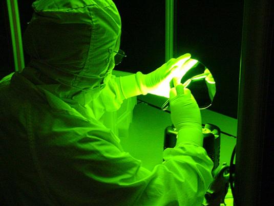
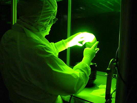
10K Lux inspection
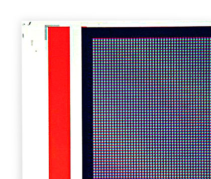
Color filter for LCD
| Guidelines to Develop Your Product (with TFD Supplied TCO's) |
|||||
|---|---|---|---|---|---|
| I.T.O. | I.Z.O. | A.Z.O. | F.T.O. | W.R.T.C.O.™ (VIS-NIR) |
|
| Applications | Displays/ LCD/OLED | Displays | Displays/Solar | Solar/ Plasma | Military Filters |
| Wave Lengths | 400-700nm | 400-700nm | 400-1500nm | 400-1500nm | 400-2500nm |
| TFD Process | Planar Ion Beam Magnetron Sputtering (IBS) |
IBS | IBS | CVD | IBS |
| Resistivity (commonly available) |
1-500 Ω/ Sq | 10-100 Ω/ Sq | 30-2000 Ω/ Sq | 7-30 Ω/ Sq | 10-50 Ω/ Sq |
| Optical Index (n,k) | (Visible Spectrum) See Data Below |
See Data Below | See Data Below | See Data Below | See Data Below |
| Surface Roughness @1450-2000Å |
7Å (RMS) | 7Å (RMS) | 7Å (RMS) | 3-50Å (RMS) | 15Å (RMS) |
| Work Function | ≥ 4.8 ev | ≥ 4.7 ev | 4.3- 4.5 ev | 4.3- 4.5 ev | ≥ 4.6 ev |
| Etchability/Quality CD (Critical Dim) |
≤ 5 μm Features/excellent |
≈10μm /good | ≥10μm /good | ≥50μm /good | ≥10μm /good |
| Uniformity 14"x14" and 24"x24" |
± 2.5% across | ||||
| Dimensions Available | 18" x 20" / 28" x 36"or smaller | ||||
| Shapes | Flat, Curved, Domed, Cupped, and Rod | ||||
| Coated Substrates Available |
Glass, Float, Borofloat, Corning, Sapphire, Quartz, Silicon | ||||
| Mil- Spec: Mil T% & Ref% 14860B Adhesion/Abrasion Mil C14806B Mil C-675B Mil C-48497 Quality Syst: Mil-I-45208 ISO 9001-2001 |
|||||
